VIOX Electric is a leading manufacturer of renewable energy electrical equipment, specializing in high-quality solar photovoltaic solutions for the global market. Our VOPV1000-3/3 Solar Combiner Box represents a premium multi-circuit solution designed specifically for advanced DC1000V solar systems requiring complete circuit independence, multi-inverter capability, and maximum operational flexibility.The VOPV1000-3/3 is a professional-grade DC combiner box engineered for high-voltage solar PV systems operating at DC1000V. This advanced 3-input, 3-output configuration features
three completely independent circuits, each with dedicated protection and control devices. Unlike combined configurations, the 3/3 architecture maintains total isolation between strings, making it ideal for multi-inverter systems, multi-MPPT applications, three-phase installations, and projects requiring maximum safety through circuit independence.
Key Features & Benefits
- Three Independent Circuits: Complete electrical isolation between all three strings – each has its own protection and output
- Multi-Inverter Ready: Perfect for systems with multiple inverters or multi-MPPT input inverters
- Maximum Circuit Independence: Each string operates completely independently with dedicated switch, SPD, and fuses
- DC1000V High Voltage Rating: Optimized for next-generation solar systems with high-efficiency modules
- Triple Protection Systems: Three complete protection sets (3 switches, 3 SPDs, 6 fuses) for ultimate safety
- 45A Per Output: Each of the three outputs rated for 45A, supporting high-power strings
- Individual Control: Operate, maintain, or isolate any string without affecting the others
- Enhanced Safety: Complete circuit isolation eliminates cross-circuit faults and simplifies troubleshooting
- Large Capacity Enclosure: VOAT-39 (296 x 550 x 130mm) accommodates three full protection circuits
- Robust Construction: IP65-rated ABS enclosure withstands harsh environmental conditions
- Three-Phase Compatible: Ideal for three-phase inverter systems with separate DC inputs
- Phased Operation Ready: Activate or deactivate individual circuits for staged commissioning
- Certified Quality: Complies with EN50539 Type 2 standards for high-voltage photovoltaic applications
Technical Specifications
General Data
| Parameter |
Specification |
| Model |
VOPV1000-3/3 |
| Rated Voltage |
DC1000V |
| Configuration |
3 Independent Inputs / 3 Independent Outputs |
| Maximum Current Per Output |
45A |
| Maximum String Current |
15A per string |
| Degree of Protection |
IP65 |
| Operating Temperature |
-25°C to +60°C |
| Maximum Altitude |
2000m (standard), >2000m on request |
| Standard Compliance |
EN50539 Type 2 |
| Insulation Voltage |
DC1500V |
| Circuit Independence |
Complete electrical isolation between all three circuits |
| Recommended System Size |
15-25kW (multi-inverter or multi-MPPT) |
Enclosure Specifications
| Parameter |
Value |
| Model |
VOAT-39 |
| Material |
ABS (Acrylonitrile Butadiene Styrene) |
| Protection Rating |
IP65 |
| Dimensions (H x W x D) |
296mm x 550mm x 130mm |
| Mounting Type |
Wall-mounted |
| Color |
Light Gray (RAL 7035) |
| Fire Rating |
Self-extinguishing, UL94 V0 flame-retardant material |
| UV Resistance |
UV-stabilized for outdoor applications |
| Cable Entry Points |
Multiple M16/M20/M25 knockouts (arranged for 3 circuits) |
| Weight |
Approximately 6.5kg (with all components) |
| Internal Layout |
Three independent circuit sections with clear separation and labeling |
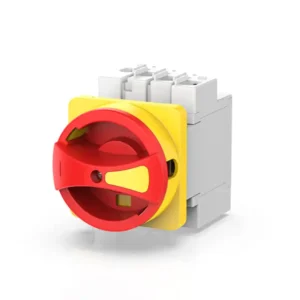
PV Switch Disconnector
| Parameter |
Specification |
| Model |
VOD1-63/4B |
| Type |
DC Load Break Switch |
| Quantity |
3 units (one per circuit) |
| Rated Voltage |
DC1000V |
| Rated Current |
45A per switch |
| Number of Poles |
2-pole (positive and negative) per switch |
| Breaking Capacity |
According to EN50539 |
| Operation |
Manual rotary operation with clear ON/OFF indication |
| Mounting |
DIN rail compatible (35mm) |
| Handle Type |
Red/Green rotary handle with padlock facility |
| Contact Material |
Silver alloy optimized for DC switching |
| Independence |
Each switch controls only its corresponding circuit |
| Electrical Life |
>10,000 operations at rated current |
| Mechanical Life |
>100,000 operations |
DC Surge Arrester (SPD)
| Parameter |
Specification |
| Model |
VO-PV1000 |
| Type |
Type 2 DC Surge Protection Device |
| Quantity |
3 units (one per circuit) |
| Maximum Continuous Operating Voltage (Uc) |
DC1000V |
| Nominal Discharge Current (In) |
20kA (8/20μs) per unit |
| Maximum Discharge Current (Imax) |
40kA (8/20μs) per unit |
| Voltage Protection Level (Up) |
≤3.5kV |
| Number of Poles |
2-pole + PE per unit |
| Response Time |
<25ns |
| Status Indication |
Visual indicator window (green = OK, red = replace) |
| Standard |
EN50539 Type 2, IEC 61643-31 |
| Mounting |
DIN rail compatible |
| Independence |
Each SPD protects only its corresponding circuit |
| Follow Current Extinction |
Self-extinguishing design |
| Thermal Disconnector |
Integrated for end-of-life protection |
DC Fuse Holder & Fuse
| Parameter |
Specification |
| Model |
VOPV-32 |
| Fuse Type |
gPV (Photovoltaic fuse) |
| Rated Voltage |
DC1000V |
| Rated Current |
15A |
| Breaking Capacity |
30kA @ DC1000V |
| Fuse Size |
10 x 38mm |
| Configuration |
6 fuse holders total (2 per string: positive and negative) |
| Fuse Links Included |
6 pieces (15A DC gPV fuse) |
| Protection Scheme |
Individual dual-pole protection for each of three strings |
| Mounting |
DIN rail compatible |
| Standard |
IEC 60269-6 |
| Indicator |
Visual fuse status indicator per holder |
| Contact Material |
Copper, tin-plated |
| Operating Temperature |
-40°C to +85°C |
Electrical Configuration
The VOPV1000-3/3 features a unique three-independent-circuit architecture that fundamentally differs from combining configurations:

Three Independent Circuit Paths:
Circuit 1:
- String 1 Input (positive + and negative -)
- Dual-pole fuse protection (2 fuses)
- VO-PV1000 surge protection device
- VOD1-63/4B switch disconnector
- Output 1 (independent feed to inverter/MPPT input 1)
Circuit 2:
- String 2 Input (positive + and negative -)
- Dual-pole fuse protection (2 fuses)
- VO-PV1000 surge protection device
- VOD1-63/4B switch disconnector
- Output 2 (independent feed to inverter/MPPT input 2)
Circuit 3:
- String 3 Input (positive + and negative -)
- Dual-pole fuse protection (2 fuses)
- VO-PV1000 surge protection device
- VOD1-63/4B switch disconnector
- Output 3 (independent feed to inverter/MPPT input 3)
Key Architectural Features:
Complete Isolation:
- No electrical connection between the three circuits
- Each circuit operates independently
- Fault in one circuit does not affect others
- Individual voltage and current characteristics maintained
Independent Protection:
- Each string has dedicated overcurrent protection (fuses)
- Each circuit has dedicated surge protection (SPD)
- Each circuit has dedicated isolation switch
- Visual status monitoring for each protection device
Independent Control:
- Individual ON/OFF control per circuit
- Independent lockout/tagout capability
- Selective maintenance without system shutdown
- Phased commissioning and operation
Terminal Configuration:
- 6 input terminals (2 per string: +/-)
- 6 output terminals (2 per circuit: +/-)
- 1 common PE (Protective Earth) terminal
- All terminals rated for DC1000V
- Input terminals: 4-6mm² cable capacity
- Output terminals: 6-16mm² cable capacity
Bill of Materials
| Item No. |
Component |
Model/Specification |
Quantity |
| 1 |
ABS Enclosure |
VOAT-39, 296x550x130mm, IP65 |
1 |
| 2 |
DC Switch Disconnector |
VOD1-63/4B, 2P, 45A, DC1000V |
3 |
| 3 |
DC Surge Arrester |
VO-PV1000, Type 2, 20kA, DC1000V |
3 |
| 4 |
DC Fuse Holder |
VOPV-32, 10x38mm, DC1000V |
6 |
| 5 |
DC Fuse Link (gPV) |
15A, DC1000V, 10x38mm, 30kA |
6 |
| 6 |
Input Terminal Block |
4-6mm², Red/Black, 1000V rated |
6 |
| 7 |
Output Terminal Block |
6-16mm², Red/Black, 1000V rated |
6 |
| 8 |
PE Terminal Block |
6-16mm², Yellow/Green |
1 |
| 9 |
DIN Rail |
35mm standard, zinc-plated |
3 |
| 10 |
Cable Glands |
M16/M20/M25, IP65 rated, 1000V |
12 |
| 11 |
Mounting Brackets |
Stainless steel 304 |
3 |
| 12 |
Circuit Separation Barriers |
Non-conductive dividers |
2 |
| 13 |
Circuit Labels |
Circuit 1/2/3 identification labels |
1 set |
| 14 |
Warning Labels |
DC1000V safety labels, multilingual |
1 set |
| 15 |
Installation Manual |
English/Multi-language, 3/3 configuration guide |
1 |
Applications
The VOPV1000-3/3 Solar Combiner Box is specifically designed for advanced solar installations requiring complete circuit independence:
Multi-Inverter Systems
- Systems with three separate string inverters
- Distributed inverter architectures
- Micro-inverter connection hubs
- Multiple small inverters for different roof sections
- Systems requiring inverter-level isolation for maintenance
Multi-MPPT Inverter Applications
- Three-MPPT input inverters (each circuit to separate MPPT)
- Optimized power harvest from different orientations
- Independent maximum power point tracking per string
- Hybrid inverters with multiple DC inputs
- High-performance inverters requiring isolated DC inputs
Three-Phase Solar Systems
- Three-phase inverter systems with separate DC inputs per phase
- Balanced three-phase power generation
- Industrial three-phase applications
- Grid-tied three-phase commercial installations
- Phase-specific power distribution requirements
Complex Multi-Orientation Arrays
- East-West-South three-orientation systems
- Different roof sections with distinct characteristics
- Mixed tilt angles requiring separate optimization
- Arrays with different shading patterns
- Optimal energy harvest from diverse conditions
Large Residential and Commercial Installations
- Premium residential systems (15-25kW) with advanced architecture
- Commercial rooftop arrays requiring maximum flexibility
- Building-integrated photovoltaic (BIPV) with multiple zones
- Industrial facilities with distributed solar generation
- Multi-tenant buildings with separate metering per circuit
Phased Installation and Expansion Projects
- Stage 1: Install Circuit 1, operate independently
- Stage 2: Add Circuit 2 without affecting Circuit 1
- Stage 3: Complete with Circuit 3 for full system capacity
- Flexibility: Each phase operates independently throughout process
High-Reliability and Safety-Critical Applications
- Systems requiring maximum fault isolation
- Critical infrastructure with redundancy requirements
- Applications demanding individual circuit control
- Projects requiring comprehensive safety documentation
- Installations with stringent compliance requirements
Monitoring and Data Acquisition Systems
- String-level performance monitoring
- Individual circuit data collection
- Advanced analytics requiring per-string data
- Fault detection and diagnostic systems
- Energy management systems with granular control
Benefits of 3/3 Independent Configuration
Complete Circuit Independence
- Total Electrical Isolation: Zero electrical connection between the three circuits
- Fault in one circuit cannot propagate to others
- Maximum system reliability through redundancy
- Simplified fault diagnosis and troubleshooting
- Enhanced safety through isolation
- Individual Circuit Control: Operate any circuit independently
- Maintenance on one circuit without system shutdown
- Selective activation for commissioning
- Independent testing and validation
- Flexible operational modes
Multi-Inverter System Advantages
- Perfect for Multiple Inverters: Direct connection to three separate inverters
- Distributed inverter architectures supported
- Optimal inverter sizing per circuit
- Inverter-level redundancy
- Individual inverter maintenance without system downtime
- Multi-MPPT Optimization: Each circuit to separate MPPT input for maximum efficiency
- Independent optimization per string orientation
- Better performance in complex shading scenarios
- Maximized energy harvest from diverse conditions
- Advanced power electronics integration
Enhanced Safety and Reliability
- Maximum Fault Isolation: Fault in one string does not affect others
- Continue operation at 67% capacity if one circuit fails
- Reduced risk of cascading failures
- Enhanced arc fault containment
- Simplified troubleshooting with isolated circuits
- Individual Protection Devices: Three complete protection sets eliminate single points of failure
- Independent surge protection per circuit
- Dedicated switching per circuit for maintenance safety
- Individual fusing prevents cross-circuit issues
- Redundant protection philosophy
Operational Flexibility
- Phased Commissioning: Activate circuits one at a time during commissioning
- Test each circuit independently
- Simplified startup procedures
- Reduced commissioning risk
- Systematic validation process
- Selective Maintenance: Service one circuit while others remain operational
- Minimize system downtime
- Scheduled maintenance without production loss
- Individual component replacement
- Simplified lockout/tagout procedures
- Mixed System Configurations: Different string configurations per circuit possible
- Varying module types or quantities per circuit
- Accommodate system changes over time
- Flexible for future modifications
- Support legacy and new components simultaneously
Performance Advantages
- Optimized Power Electronics: Each circuit optimized for its specific conditions
- Better MPPT performance with separate inputs
- Reduced losses from string mismatch
- Enhanced performance in partial shading
- Maximum energy yield from diverse orientations
- String-Level Monitoring: Precise performance data per circuit
- Identify underperforming strings immediately
- Detailed energy production analytics
- Predictive maintenance capabilities
- Enhanced system optimization
Cost-Benefit Analysis vs. 3/1 Configuration
- Higher Initial Investment but Greater Value: Three complete protection sets vs. shared components
- Larger enclosure to accommodate independent circuits
- More complex wiring but greater flexibility
- Higher component count ensures reliability
- Long-Term Operational Savings: Reduced maintenance downtime (maintain one circuit at a time)
- Better energy yield through optimization
- Lower risk of total system failure
- Simplified troubleshooting reduces service costs
- Extended system lifetime through redundancy
Ideal When:
- Using multi-MPPT inverters (maximize their capability)
- Multiple inverters in system (direct connection)
- Maximum reliability required (critical applications)
- Complex orientations (optimize each separately)
- Phased installation planned (add circuits over time)
Quality & Compliance
Certifications & Standards:
- EN50539 Type 2 – Photovoltaic (PV) systems – DC connectors for 1000V applications
- IEC 60269-6 – Low-voltage fuses for photovoltaic applications (1000V)
- IEC 61643-31 – Surge protective devices for photovoltaic installations (1000V)
- IEC 60947-3 – Low-voltage switchgear – Switches, disconnectors (1000V DC)
- IP65 – Ingress Protection (dust-tight and water jet protected)
- RoHS Compliant – Restriction of Hazardous Substances
- REACH Compliant – EU chemicals regulation
- CE Marking – European conformity
Quality Assurance Testing:
- 100% factory testing of all three independent circuits
- High-voltage withstand testing (DC1500V for 1 minute per circuit)
- Insulation resistance verification (>200MΩ @ DC1000V per circuit)
- Circuit isolation testing (>200MΩ between circuits)
- High-temperature aging tests (96 hours at 70°C)
- Thermal cycling tests (-40°C to +85°C, 100 cycles)
- Mechanical stress testing (vibration and impact per IEC standards)
- Contact resistance measurement on all terminals (<30μΩ)
- All three surge protection devices tested per IEC 61643-31
- UV aging test for enclosure materials (1000 hours)
- Independent operation verification for all three circuits
Manufacturing Excellence:
- ISO 9001:2015 certified manufacturing facility
- ISO 14001:2015 environmental management system
- Strict quality control procedures for multi-circuit assemblies
- Premium component selection from certified suppliers (UL, TÜV listed)
- Specialized assembly process for independent circuit architecture
- Manual inspection of all electrical connections and isolation barriers
- Comprehensive final inspection and functional testing per circuit
- Complete traceability system for all components and assemblies
- Continuous improvement programs based on field performance data
Installation & Maintenance
Installation Guidelines
Site Selection for Multi-Circuit Installation:
- Mount in a well-ventilated location with easy access for maintenance
- Ensure protection from direct sunlight, rain, and water accumulation
- Minimum clearance of 200mm on all sides for ventilation and access
- Consider cable entry paths from three different string locations
- Position for easy visual inspection of all three SPD indicators
- Ensure sufficient space for future service access to individual circuits
Mounting Procedure:
- Use appropriate mounting hardware rated for enclosure weight (6.5kg + cables)
- Ensure level installation using spirit level (critical for larger enclosure)
- Verify enclosure is securely fastened (minimum 6 fixing points due to size)
- Maintain IP65 protection rating after installation
- Consider load distribution on mounting surface due to weight
Circuit Connection Sequence:
- Label all three circuits clearly before connection (Circuit 1, 2, 3)
- Connect circuits in numerical order for systematic installation
- Critical: Maintain complete separation between circuits during wiring
- Verify correct polarity for each circuit before termination
- Use cables rated for DC1000V with appropriate temperature rating
- Input cables: 4-6mm² (15A max per string)
- Output cables: 6-16mm² (to accommodate 45A capacity)
Independent Circuit Wiring:
- Route Circuit 1, 2, and 3 cables separately to avoid confusion
- Use consistent color coding within each circuit (Red +, Black -)
- Maintain physical separation between circuit cables where possible
- Label all cables clearly with circuit number
- Apply proper torque to all terminals (1.2-1.5 Nm as specified)
- Ensure proper cable entry sealing with appropriate glands
Pre-Commissioning Checks (Per Circuit):
- Perform insulation resistance test on each circuit (minimum 200MΩ @ DC1000V)
- Verify insulation between circuits (minimum 200MΩ between any two circuits)
- Verify continuity of PE connection (common to all circuits)
- Check all mechanical connections for tightness in each circuit
- Confirm all three SPD indicators show green (operational status)
- Test each switch disconnector operation individually under no-load
- Verify all cable glands are properly sealed
- Measure open-circuit voltage of each string independently
- Critical: Verify no electrical connection exists between circuits
Phased Commissioning Procedure:
- Commission Circuit 1 first, verify operation
- Commission Circuit 2, ensure Circuit 1 unaffected
- Commission Circuit 3, verify all three operate independently
- Confirm isolation: disconnect each circuit individually while others operate
Safety Precautions
Multi-Circuit Safety Considerations:
- Critical: Even with one circuit disconnected, other circuits remain energized
- Never assume entire system is de-energized until ALL THREE circuits verified
- Use multi-point voltage testing on all three circuits independently
- Implement lockout/tagout procedures with THREE SEPARATE LOCKS if working on all circuits
DC1000V Multi-Circuit Safety:
- Qualified personnel only – specialized multi-circuit training required
- Always use appropriate PPE: insulated gloves (Class 2), safety glasses, arc-rated clothing
- Use CAT III 1000V rated test equipment only
- Be aware that capacitive charge may remain in cables after disconnection
Operational Safety:
- Always open the specific switch disconnector before accessing that circuit’s components
- Wait minimum 5 minutes after disconnection before opening enclosure
- Use voltage detector to verify absence of voltage on the specific circuit
- Test adjacent circuits to ensure they remain isolated
- Never exceed rated voltage (DC1000V) and current specifications
- Do not operate switch disconnectors under load
- Maintain clear identification of which circuit is being serviced
Maintenance Recommendations
Regular Inspection (Every 6 Months):
- Visual inspection of all three circuits for signs of damage or overheating
- Check all three SPD indicators (green = OK, red = replace immediately)
- Inspect enclosure for cracks, damage, or compromised seals
- Verify cable glands maintain proper seal integrity on all circuits
- Check for any signs of moisture ingress
- Inspect each circuit’s fuse status visually
- Verify circuit separation barriers remain intact
Annual Maintenance (Per Circuit):
- Verify all connections remain tight in each circuit (retorque: 1.2-1.5 Nm)
- Test each switch disconnector operation individually under no-load
- Perform insulation resistance test on each circuit (should be >200MΩ)
- Test insulation between circuits (should be >200MΩ between any pair)
- Clean enclosure exterior with damp cloth
- Inspect internal components in each circuit for signs of aging
- Verify string voltage on each circuit independently
Component Replacement (Per Circuit):
- Replace fuses only with identical specifications (15A gPV, DC1000V, 10x38mm, 30kA)
- Always replace fuses in pairs (positive and negative) for same circuit
- SPD replacement: only use VO-PV1000 or equivalent approved model
- When replacing SPD, only that circuit needs to be de-energized
- Maintain detailed maintenance log for each circuit separately
- Record component replacements per circuit for trend analysis
Independent Circuit Troubleshooting
| Symptom |
Possible Cause |
Solution |
| Circuit 1 no output, Circuits 2&3 OK |
Circuit 1 fuse blown |
Check/replace Circuit 1 fuses only, others unaffected |
|
Circuit 1 switch OFF |
Turn Circuit 1 switch to ON |
| All three circuits no output |
Common issue upstream |
Check array-level connections |
|
All three switches OFF |
Verify all switches in ON position |
| One circuit overheating |
Loose connection in that circuit |
Retorque terminals in affected circuit only |
|
Undersized cable |
Verify and upgrade cable for that circuit |
| One SPD indicator red |
That circuit’s SPD end-of-life |
Replace SPD in affected circuit, others continue operating |
| Unbalanced output between circuits |
Different string configurations |
Verify each string design independently |
|
Module degradation in one string |
Investigate specific circuit’s performance |
| Frequent fuse failure (one circuit) |
Short circuit in that specific string |
Inspect string for that circuit only |
|
Overcurrent condition |
Verify that circuit’s string design <15A |
| Two circuits normal, one intermittent |
Faulty component in intermittent circuit |
Isolate and diagnose that circuit independently |
Technical Comparison: VOPV1000-3/3 vs VOPV1000-3/1
| Feature |
VOPV1000-3/3 |
VOPV1000-3/1 |
| Architecture |
3 Independent Circuits |
3 Inputs Combined to 1 Output |
| String Inputs |
3 |
3 |
| Outputs |
3 Independent |
1 Combined |
| Circuit Isolation |
Complete (no connection) |
Combined (parallel connection) |
| Enclosure Size |
296x550x130mm (VOAT-39) |
296x230x120mm (VOAT-13) |
| Switch Disconnectors |
3 units (one per circuit) |
1 unit (after combining) |
| SPD Units |
3 units (one per circuit) |
1 unit (after combining) |
| Fuse Holders |
6 (2 per string) |
6 (2 per string) |
| Weight |
~6.5kg |
~3.5kg |
| Ideal Application |
Multi-inverter, multi-MPPT |
Single inverter, combined feed |
| Circuit Control |
Individual per circuit |
All circuits together |
| Fault Isolation |
Complete (one circuit fails, others OK) |
Partial (fault may affect combined output) |
| Maintenance Downtime |
Minimal (service one, others run) |
Full system (must disconnect all) |
| Multi-Inverter Support |
Excellent (direct connection) |
Not applicable |
| Multi-MPPT Support |
Excellent (separate MPPT per circuit) |
Limited (combined input) |
| System Size |
15-25kW |
10-15kW |
| Cost |
Higher (triple protection) |
Lower (shared protection) |
| Flexibility |
Maximum |
Moderate |
| Best For |
Complex systems, maximum reliability |
Simple systems, cost optimization |
Why Choose VIOX VOPV1000-3/3?
- Unmatched Circuit Independence: Three completely isolated circuits eliminate cross-circuit interference, maximizing system reliability and allowing operation even if one circuit issues occur.
- Multi-Inverter System Excellence: Direct connection to three separate string inverters, ideal for distributed architectures and advanced multi-MPPT systems.
- Superior Safety Architecture: Triple protection systems eliminate single points of failure, with individual circuit control for safer maintenance and simplified lockout/tagout.
- Maximum Operational Flexibility: Supports phased commissioning, selective maintenance, and mixed configurations to adapt to changing system requirements.
- Professional Engineering: Large VOAT-39 enclosure with optimized internal layout, premium DC1000V components, and enhanced insulation coordination.
- Advanced System Capabilities: Supports string-level monitoring, smart solar installations, and sophisticated energy management systems.
- Long-Term Value: Higher reliability reduces total cost of ownership, minimizes maintenance downtime, and extends system lifetime through redundancy.
Get in Touch
Ready to implement the ultimate multi-circuit solution with the VOPV1000-3/3 Solar Combiner Box? Contact VIOX Electric today for:
- Detailed technical specifications and CAD drawings
- Multi-inverter and multi-MPPT system design consultation
- Independent circuit configuration optimization
- Competitive pricing and MOQ (Minimum Order Quantity) information
- Custom configuration options for specific project requirements
- Technical guidance on complex multi-circuit installations
- Sample orders for testing and evaluation
- Bulk order quotations with volume discounts
- Delivery timeline and international logistics support
- Specialized installation training for 3/3 independent configuration
- Product certifications and compliance documentation
- Integration support for multi-inverter systems
- String-level monitoring system recommendations